NEXT ROBOTTECHDATA CENTER EPC
08 — 10Power train, backup & thermal

Capacity, Tier and density are decided here

Two systems carry the entire facility: the power train from the grid connection down to the rack PDU, and the thermal loop from the chip back out to the sky.

07Power infrastructure

From the grid to the rack

Everything else in a data center is negotiable. The power train is not — it defines the capacity, the Tier, the CAPEX and, for an AI campus, whether the project is possible at all.

01
Grid 110–220 kV
Dual independent feeders
02
Substation
Air or gas insulated switchyard
03
Transformers
40–63 MVA, oil, blast walls
04
MV switchgear
20/10 kV, selective protection
05
UPS
Modular, 1.25–2.5 MW blocks
06
Busway
Overhead, 800–1250 A
07
Rack PDU
Metered, dual feed A/B
08
Rack
Up to 150 kW liquid cooled
Redundancy architecture

One redundant unit per capacity block

Design availability99.98%
Relative CAPEX1.25×
Independent paths1
Failure behaviour

Survives one component failure

N
1.00×
N+1
1.25×
2N
1.70×
2N+1
2.05×
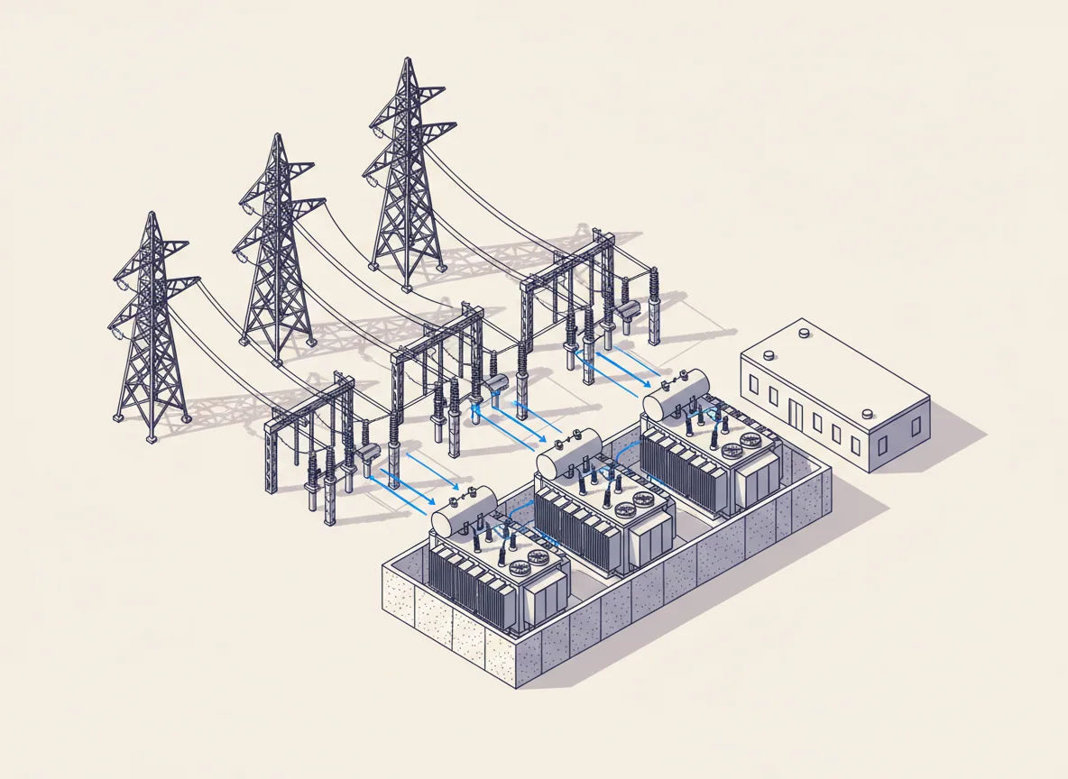
Dedicated data center substation
Dedicated substation: incoming lines, switchyard, three power transformers inside blast walls.
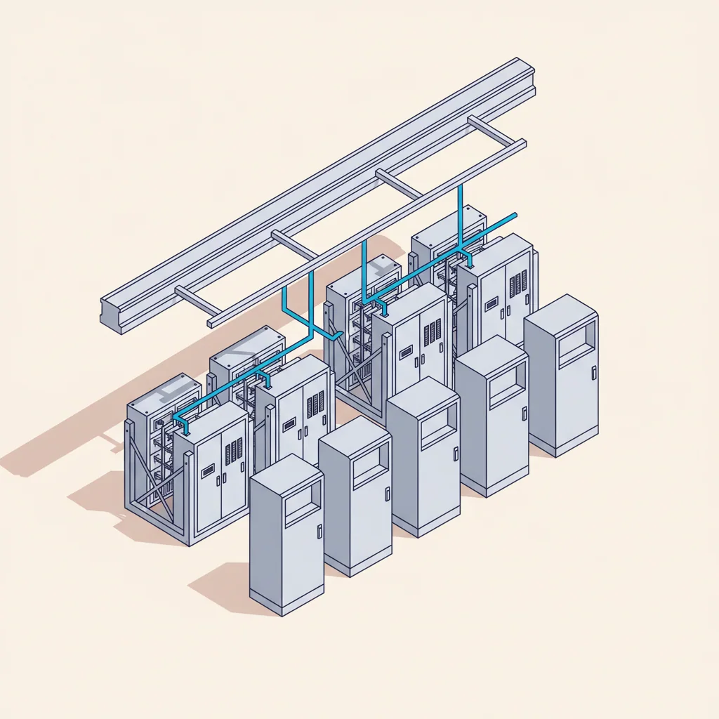
UPS and battery room
UPS & battery room
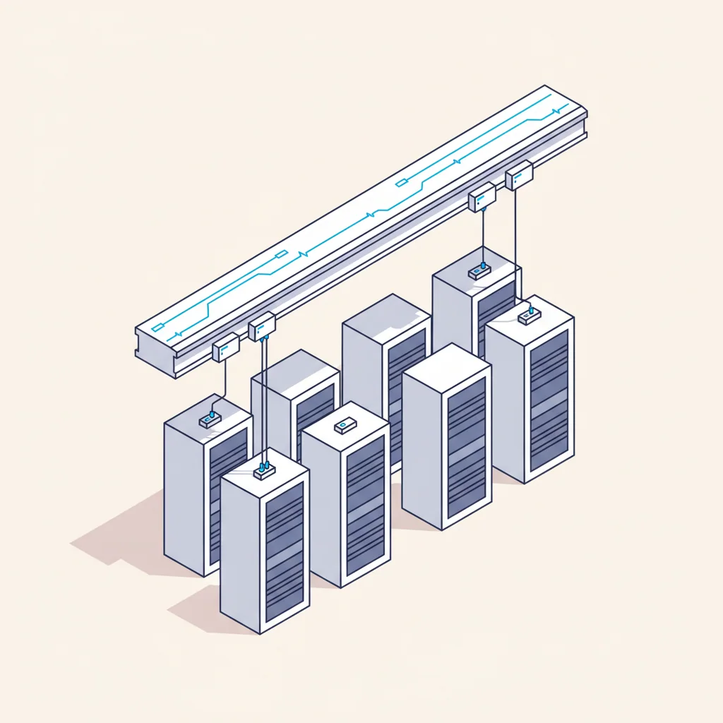
Overhead busway distribution
Overhead busway to rack PDU
08Backup power

Grid failure is a design case

The utility will fail. What matters is that the IT load never notices. Run the sequence and watch where the load sits at every second.
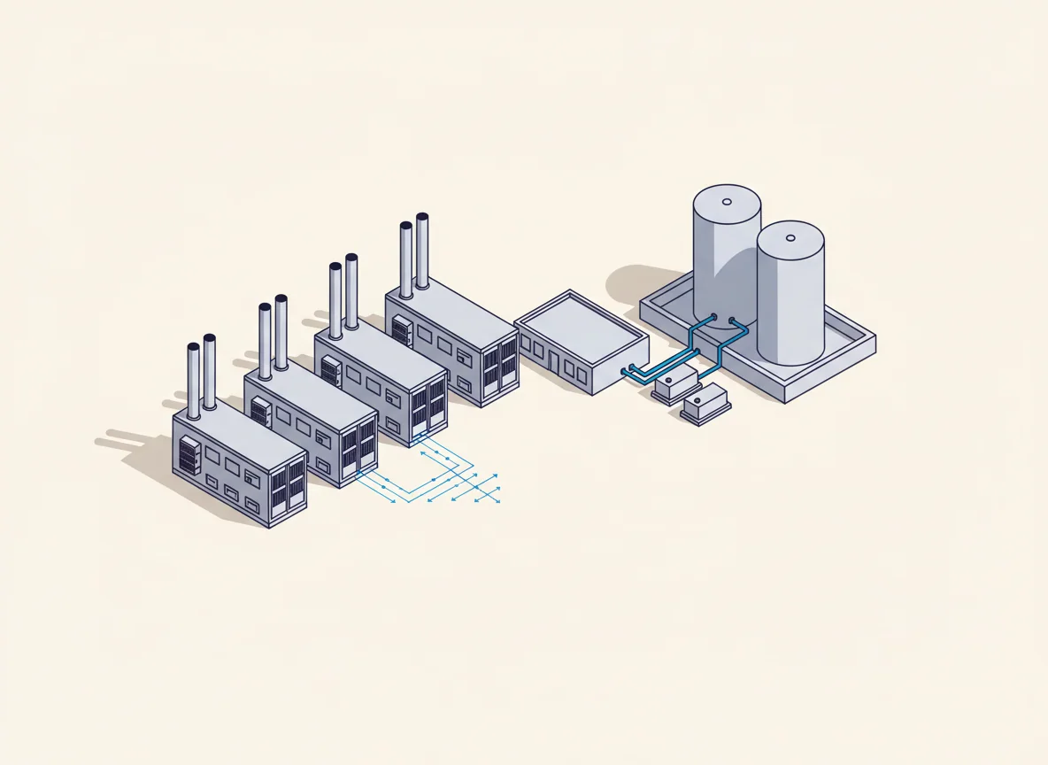
Backup generator yard
Capacity4 × 3.0 MVAAutonomy72 hStart time≤ 10 sRedundancyN+1
Transfer sequenceREADY
Utility feed
Online
UPS
Standby
Generators
Standby
IT load
Uninterrupted
  1. 0 msGrid failure detected
  2. 0 msUPS carries the full IT load
  3. 2 sGenerator start signal
  4. 10 sGenerators at rated speed
  5. 13 sParalleling and synchronisation
  6. 15 sATS transfers load to generators
  7. 20 sCooling plant restarted in sequence

Verified on site during L3 and L4 commissioning at full load bank.

09Cooling infrastructure

Density decides everything

A 10 kW rack and a 120 kW rack are different buildings. Pick the density you need and the cooling architecture that can actually carry it appears.
Target rack density
80kW / rack
80 kW
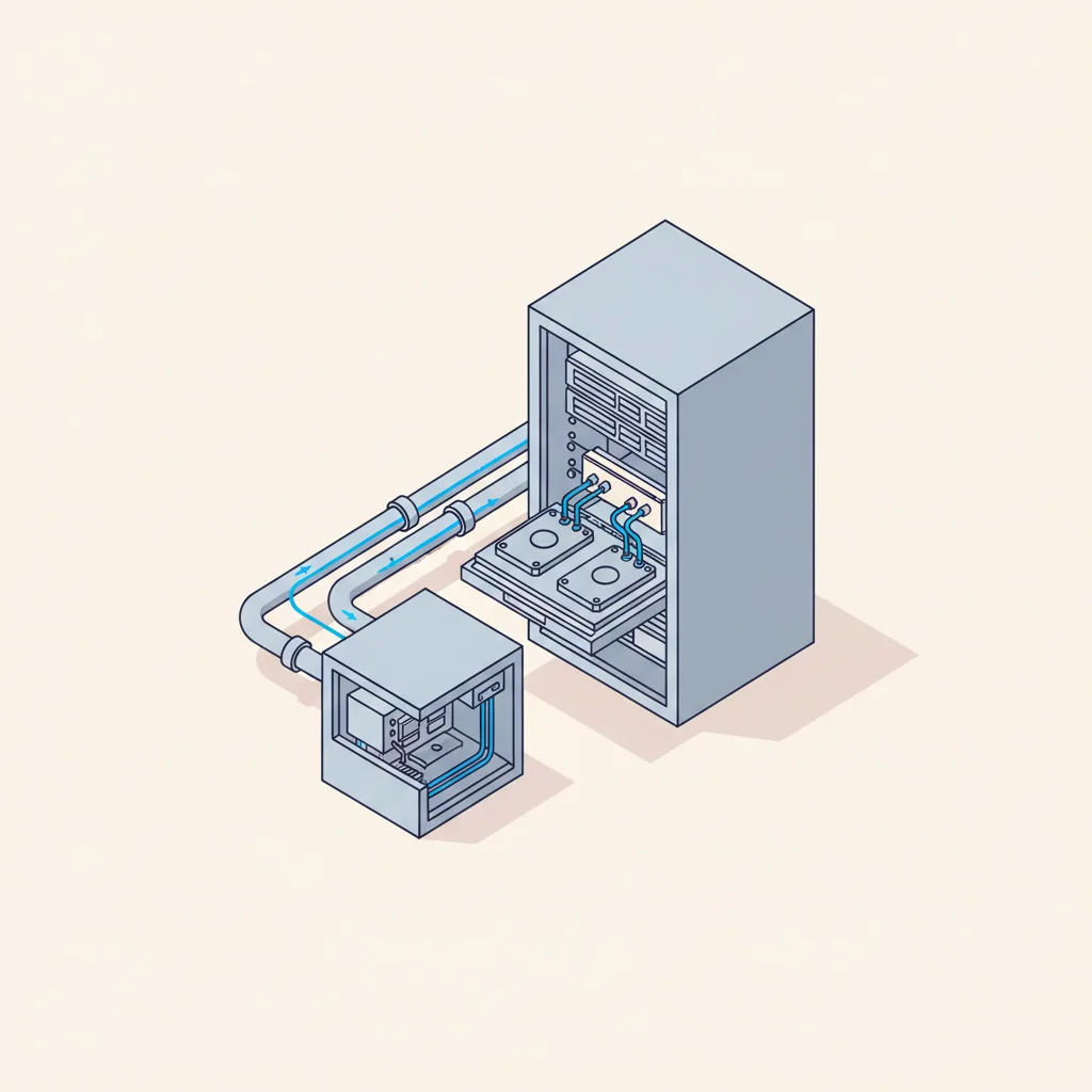
Direct-to-chip liquid
The default for AI training halls: 70–80% of heat captured in liquid.
Selected architecture

Direct-to-chip liquid

  1. 01GPU cold plate
  2. 02Rack manifold
  3. 03CDU
  4. 04Heat rejection
Max density150 kW
PUE1.10–1.20
Water useClosed technical loop
Supported now2 / 3
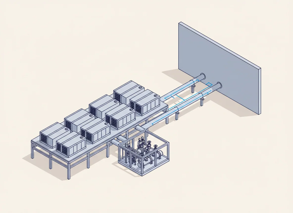
Cooling plant yard
Plant yard: dry coolers, chillers, pump house and insulated pipe racks into the hall.
Next step

Tell us what you are building

Send the site status, the grid offer and the target load. You get a concept, a power and cooling strategy and an indicative CAPEX back.

Start a project